Analog electronics Experiment 10 aim To study and plot the characteristics of MOSFET in its various configurations.
Note remember page numbers
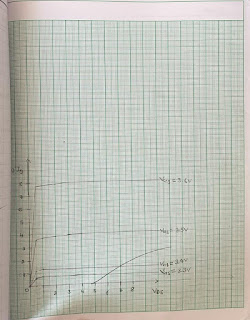
Aim: To study and plot the characteristics of MOSFET in its various configurations.

Apparatus:
Bread board, variable and fixed D.C. Sources, MOSFET, resistances, multimeters, connecting
wires.
OR
FET Characteristics trainer kit with connecting leads and power supply.

Theory: A metal–oxide–semiconductor field-effect transistor (MOSFET) is based on the
modulation of charge concentration by a MOS capacitance between a body electrode and
a gate electrode located above the body and insulated from all other device regions by a gate
dielectric layer which in the case of a MOSFET is an oxide, such as silicon dioxide. If dielectrics
other than an oxide such as silicon dioxide (often referred to as oxide) are employed the device
may be referred to as a metal–insulator–semiconductor FET (MISFET). Compared to

the MOS
capacitor, the MOSFET includes two additional terminals (source and drain), each connected to
individual highly doped regions that are separated by the body region. These regions can be
either p or n type, but they must both be of the same type, and of opposite type to the body

region. The source and drain (unlike the body) are highly doped as signified by a "+" sign after
the type of doping.

If the MOSFET is an n-channel or N-MOS FET, then the source and drain are "n+" regions and
the body is a "p" region. If the MOSFET is a p-channel or P-MOS FET, then the source and
drain are "p+" regions and the body is a "n" region. The source is so named because it is the
source of the charge carriers (electrons for n-channel, holes for p-channel) that flow through the

channel; similarly, the drain is where the charge carriers leave the channel.
The occupancy of the energy bands in a semiconductor is set by the position of the Fermi
level relative to the semiconductor energy-band edges. As described above, and shown in the
figure, with sufficient gate voltage, the valence band edge is driven far from the Fermi level, and
holes from the body are driven away from the gate. At larger gate bias still, near the
semiconductor surface the conduction band edge is brought close to the Fermi level, populating
the surface with electrons in an inversion layer or n-channel at the interface between the p region
and the oxide. This conducting channel extends between the source and the drain, and current is
conducted through it when a voltage is applied between the two electrodes. Increasing the
voltage on the gate leads to a higher electron density in the inversion layer and therefore
increases the current flow between the source and drain.
For gate voltages below the threshold value, the channel is lightly populated, and only a very
small sub-threshold leakage current can flow between the source and the drain.
When a negative gate-source voltage (positive source-gate) is applied, it creates a p-channel at
the surface of the n region, analogous to the n-channel case, but with opposite polarities of
Comments
Post a Comment