Note remember page numbers
Aim To design the 4-bit synchronous counter. .
Apparatus Required: Experimental Kit, IC- 74190, & Connecting Wire.
THEORY:
The ripple counter is the simplest to build, but there is a limit to its highest operating
frequency. 4 flip flops are used to construct 4- bit Synchronous counter. Every flip flop is
triggered in synchronism with the clock. The construction of that type of parallel binary counter
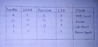
is shown in figure 1, along with the truth table and the waveforms for the natural count sequence.

The basic idea here is to keep the J and K inputs of each flip flop high, such that the flip flop will
toggle with any negative clock transition at its clock input. We then use AND gates to gate
every second clock to flip flop B, every fourth clock to flip flop C, and so on. This logic
configuration is after referred to as “steering logic” Since the clock pulses are gated or steered to
each individual flip flop.
The clock is applied directly to flip flop A. Since the JK flip flop used responds to a negative
transition at the clock input and toggles when both the J and K input are high. Flip flop A will
change state with each negative clock transition. Whenever A is high. AND gate X is enable and
a clock pulse is passed through the gate to the clock input of flip flop B. Thus B changes state
with every other negative clock transition at points b, d, f and h on the time line. Since AND gate
y is enabled and will transmit the clock to flip flop C only. When both A and B are high. Flip
flop C changes state with every fourth negative clock transition at points d and h on the time line.
Examination of the waveform and the truth table reveals that this counter progresses upward in a
natural binary sequence from count 000 up to count 111, advancing One count with each
negative clock transition. This is a mode 8 parallel or synchronous, binary counter operating in
the count up mode.


PROCEDURE:
1. Make the connections as shown in the pin diagram.
2. Connect Pin No- 8 to GND.
3. Connect Pin No- 16 to Vcc.
RESULT: The Observation table of Synchronous counter is verified.
PRECAUTION:
1. All Connections should be according to Pin diagram.
2. All Connections should be right and tight.
3. Reading should be taken carefully.
4. Switch off Power supply after completing the Experiment.
Comments
Post a Comment