Note remember page numbers
Aim: To study the gain and plot frequency response of single stage amplifier.
Apparatus:
CRO, function generator, breadboard, transistor BC 104 (1 pcs), capacitor 10F (3 pcs), 100F
(2pcs), resistor 4.7K (2pcs), 5.6K (2pcs), 1K (2pcs), 12 V supply and connecting leads.
OR
Function generator, RC Coupled Amplifier Trainer kit, CRO, CRO Probes, connecting leads and
power supply.
Theory:
Common emitter amplifiers give the amplifier an inverted output and can have a very
high gain that may vary widely from one transistor to the next. The gain is a strong function of
both temperature and bias current, and so the actual gain is somewhat unpredictable. Stability is
another problem associated with such high gain circuits due to any unintentional positive
feedback that may be present.
Other problems associated with the circuit are the low input dynamic range imposed by
the small-signal limit; there is high distortion if this limit is exceeded and the transistor ceases to
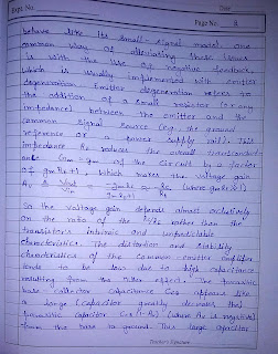
behave like its small-signal model. One common way of alleviating these issues is with the use
of negative feedback, which is usually implemented with emitter degeneration. Emitter
degeneration refers to the addition of a small resistor (or any impedance) between the emitter and
the common signal source (e.g., the ground reference or a power supply rail).


This
impedance reduces the overall transconductance of the circuit by a factor
of , which makes the voltage gain
So the voltage gain depends almost exclusively on the ratio of the resistors rather than
the transistor's intrinsic and unpredictable characteristics. The distortion and stability
characteristics of the circuit are thus improved at the expense of a reduction in gain.
The bandwidth of the common-emitter amplifier tends to be low due to high capacitance
resulting from the Miller effect. The parasitic base-collector capacitance appears like a
larger parasitic capacitor (where is negative) from the base to ground. This
large capacitor greatly decreases the bandwidth of the amplifier as it makes the time constant of
the parasitic input RC filter where is the output impedance of the signal
source connected to the ideal base.


Procedure:
(1) Apply input signal of 10 mv amplitude and frequency 50 Hz at input terminal.
(2) Varying the frequency of the input signal from 10Hz to1MHz.
(3) Measure the output signal amplitude.
(4) Study the frequency response characteristics of single stage amplifier.
Conclusion: The gain of single stage amplifier has been studied and frequency response is
observed. Also, reduction in gain is observed due to high input parasitic capacitances..
Precautions:
1. Do not use open ended wires for connecting to 230 V power supply.
2. Before connecting the power supply plug into socket, ensure power supply should be
switched off.
3. Ensure all connections should be tight before switching on the power supply.
4. Take the reading carefully.
5. Power supply should be switched off after completion of experiment.


Comments
Post a Comment